> const int AUDIO_IN = A7;> Should I change itYes. You can use the SpeechRecog1.exe Windows program simply to record and playback the outputs from the digital filters in the Arduino. That is to make sure that e.g. What can we do to recognise an utterance? The program has stored the previous 2 input values and the previous 2 output values. So "importance" is 1/ (50+standard deviation). In speech recognition, it's common to apply "Dynamic Time Warping" to recorded utterances. Most people seemed to be pretty pleased just to have made some recordings, done a Fourier transform and drawn some graphs. Each of the examples is shifted to the left or right until it best matches the template for that utterance. 1 year ago, I'm happy to give the source away. I uploaded the Delphi source to github about 3 months agohttps://github.com/peterbalch/SpeechArduinoIf you want to run it on a Raspi then you could try Lazarus. Neither worked well for me.  The sketch can send the values to the PC over the serial line but serial transmission slows it down to around 1100sps (at 57600baud). The Gain pin controls the gain of the AGC: In the circuit shown above, I have left A/R unconnected. Multiplication takes around 50% longer. From now on, I treat the 5 bands equally. The edition I have is available herehttps://www.amazon.com/Automatic-Speaker-Recognitiothers are here:https://trove.nla.gov.au/work/8985466https://books.google.co.uk/books?id=nFZTAAAAMAAJ&sOf course, it's way out of date now but the technology they were using back then is similar to a low-end micro today.I haven't looked for the individual papers online - surely many must be available for free by now.I can photograph the contents page if you like then you can search for them.Peter. C1 and R4 act as a high pass filter with a gentle roll-off below 1.5kHz. 1 year ago, Thanks.It's an old book I happen to have in my bookcase. But the Pascal will be identical.If it were me, I'd just start from scratch in your favourite language. An LM358 is a pretty poor op-amp. the amplitude. We also have to collect the data from the ADC, calculate the amplitude of the bands and store the results in an array.
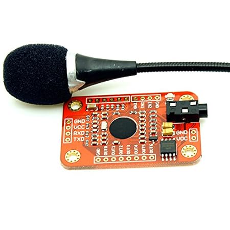
However, the program was hacked around a lot as I tried various methods of analysis so it's not neccessarily easy to follow. Click the Utterances|RecordTraining menu item to start recording utterances. Those are built by a large team of specialised engineers, have a supercomputer to help out, and are still prone to errors. I think I will use SOPARE on a raspberry Pi for this. The diagram above shows a typical filter. The LM358 is powered from the 5V output of the Nano. But an IIR filter is less stable. I must have bought it years ago. You must read ADCL and ADCH in the correct order. We would prefer to be doing other things while the ADC is waiting for the conversion so I do it differently. DrDiettrich: I used an LM358. For a start you need a microphone and amplifier module, readily available for near nothing. The extra errors produced by bad matches exceed the improvement produced by good matches. Or what about a remote-control robot? You can have nearly as much fun making something that understands "LED", "ON", MOVE", "ONE", TWO", "THREE", etc. The speechrecog2.ino sketch uses the templates to recognise utterances. (Later on you can record your own.). The the overall difference is. Support Vector Machines (SVM) are supposed to be able to circumvent that problem but I've no experience of using them. The speechrecog2.ino sketch sends the text of the recognised word to the PC over the serial line but you would use it in you project to control something. Now you can click the "Test Templates" tab and record a training set. It's not a difficult algorithm.Peter. The problem is that you can apply Warping to make an utterance match the correct template better but it also makes the utterance match the wrong templates better. Make sure the ADC pin you connect the op-amp to matches the one defined in the sketch. In that case, a SPEECH recognition module is better. 6 months ago. The Arduino ADC has 10 bits so the numeric value goes from 0 to 1023. I was wondering whether converting the filter outputs (on the Arduino) into spreadsheet input (on a PC) would be useful. Q is the "Q-factor" which is 1 / (the width of the band). I tried applying Dynamic Time Warping to the incoming utterance when comparing it with the templates. It filters the samples into 4 frequency bands plus ZCR and stores 13 segments of data each 50mS long. But it will run at 5V and is good enough for this project. The higher the order the more control you have over the filter's response curve. 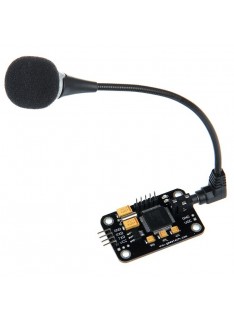 When you read ADCL, the value in ADCH is frozen until you read it too. An "IIR" is a "recursive filter".). The Arduino divides the whole utterance into "segments" each 50mS long (in some of the literature, they're called "frames"). You should use a little hysteresis which calculating ZCR so as not to pick up low-level noise. That's what I'm going to attempt. arduino recognition module voice v3 kit compatible Once the 13 segments have been stored, we have to choose which of our sample words we think those 65 numbers most resembles. Wouldn't I be able to try to record 2 copies of speech, one normal and one with distortion? all the "three" utterences are roughly the same loudness. Once again click the Utterances|Recognise|RecogniseAll menu item to compare each of the training examples with each template. In the Utterances|Recognise sub-menu, check the OnArduino menu item. With higher gains, background noise is amplified too much; when there was speech, the AGC reduced the speech signal to reasonable level but when you stopped speaking, the noise slowly returned. It's easier to get the maths wrong for an IIR filter so that he output goes crazy or gets stuck. The ADIE bit (ADC Interrupt Enable) has been cleared by the Arduino library so no actual interrupt happens - we just use the Interrupt Flag to check when the ADC conversion is finished. But the Pascal will be identical.If it were me, I'd just start from scratch in your favourite language. I totally get your concern about having to support old code. Multilayer neural nets can recognise patterns that are not linearly separable but, in my limited experience, require huge amounts of training data. Thanks a lot. Which template is most like that example? . As a result, we're limited to maybe a dozen arithmetc operations per sample. When you have got a set of templates that you're happy with, you can export them to the Arduino as the Templates.h file. It was fun, but I didn't have a real computer to learn C with, and I only recently got my arduino back out to try to learn how to use it as well. KingDubDub: It's done that way to ensure that you don't mix up low and high bytes from different samples.
The speechrecog2.ino sketch (download: step 10) is compiled using the Templates.h file and the Coeffs.h file. A single word is so short that Dynamic Time Warping is not useful. I found a gain of 40dB gave the best signal-to-noise ratio with the microphone on a boom near my mouth. A "three" often looked like a "seven" and a "four" looked like a "zero". I have been looking at the Geetech Voice Module, but I am concerned that it may not have space for, say, 2 gigs of phrases. The result is a 16-bit int centred on 0. The ADIF bit (ADC Interrupt Flag) is set once a conversion is complete. I chose the MAX9814 microphone amplifier as it has automatic gain control. Of course, there are big individual differences. As I said in the introduction, this an "experimental" project - something for you to work on and improve. We can't afford more than a second order IIR filter. Most groups had a PDP-8 or PDP-11. Usually, when you click on a grid square, the utterance is recognised on the PC. The utterance is assumed to start when a the total energy in the bands exceeds a threshold. After you have recompiled the speechrecog1.ino sketch, it gets sample utterances and sends them to the PC so the PC can calculate the "templates". Do you mean write your own Windows code? Within each segment it measures the amplitude of each of the 5 bands.The utterance is assumed to have 13 segments so that's a total of 65 16-bit ints covering 0.65 sec. v3 An Arduino with an ATmega328 is not fast enough to do that as the sound arrives and not big enough to hold the samples of a complete utterance for later analysis. Isn't its own microphone alone enough?Thanks. Or do you have a shortlist of such modules already? That way thoseof us inclined to work the code further can just fork your repo, butothers would be always able to go back to your original code. (An ATmega328 can use existing LPC coefficients to produce speech in real time but it can't calculate the coefficients.). Type strings for those utterances into the memo at the left of the window. But you might have more success with them. HiI have two question. The digital filter coefficients are exported as the Coeffs.h file. Decide how many different utterances you want to recognise - for instance 10 for the digits "zero" to "nine". Voice Command | Android apps | Arduino | AI2, Arduino Tutorial Control LED by voice (via Bluetooth), How to genrate codes for jarvis voice home automation arduino project, How to Voice Controlled Automation Using ARDUINO MEGA (HC06 Bluetooth Module), How to Make Your Own Sound and Voice Reactive LEDs using Arduino, Speech Synthesis Shield for Arduino Demo (DFR0273), HOW TO MAKE ARDUINO VOICE CONTROL CAR USING L293D, How to: Arduino Voice / Speech Recognition with Geeetech Module [Tutorial], How to make Arduino speak through your smartphone? What sort of accuracy were you getting? Similarly, quadratic discriminant analysis (QDA) is supposed to work with non linearly separable data but I have no experience of it either. The most obvious would be linear discriminant analysis. Then use SpeechRecog1.exe to stored some training and test utterances as described in Step 9. I've no idea what polytomous multinomial logistic regression is but it sounds cool. I found something under Q=2 is about right. The Q value depends on how far apart the bands are. You could connect the module directly to one of the ADC input pins but in the diagram above I have included a simple RC high-pass filter. If you click on left hand column of the grid, the mean and S.D. as in making something that understands "Hey robot, hoof it on down the road 12 whatevers". I've used it - it's a nice system. I have a friend who has messed with Linux before, and he agreed that SOPARE is a good system. We must do much of the analysis in real-time as the samples arrive. The lowest distance is the best and that one is displayed in the grid as the best match. module voice recognition arduino compatible It's been hacked and modified so much it's not really readable. Click the Utterances|Recognise|RecogniseAll menu item to compare each of the training examples with each template. How to make voice reacted leds with arduino without sound sensor!Lets do it!!!!!!!! Any chance to release the source of the exe? The Q factor should be the same for all bands which implies they have to be equally spaced on a logarithmic scale. You already have that.Is there anything you need to know? Because this system is for recognising a single speaker's voice, it should be tuned to that speaker. For a bandpass filter, the order of the filter determines how steeply the filter rolls-off above and below the pass frequency. An MP3 player while jogging? The mean and S.D. Perhaps you want a head-mounted multimeter or a tiny ear-mounted mobile phone with no screen or keyboard. A MAX9814 includes a microphone amplifier and an AGC (Automatic Gain Control). A more appropriate way of dividing the data into bands is by using digital filters. I allow the whole utterance to shift by up to (e.g.) No problem! Just have ten "templates" for the ten different digits and measure the difference between the incoming data and each of the templates. The amplitude of each band in each segment is measured. arduino How? Reading my IEEE book from the 1970s gave few descriptions of what people did back then. The band amplitude values are compared with the template values. Can it do anything useful at all? recognition GAIN = Unconnected, uncompressed gain set to 60dB. In the image above, the frequency axis (x-axis) is linear. Click the "Templates" tab then the "Train Templates" tab to view some utterances with which to calculate the templates. on Step 5. I did some research on speaker recognition back in the 90's and I used an old (really old) edition of Transactions of the IEEE much like you did. You can write your own version of speechrecog2.ino with your own algorithm.
The results are not great. For instance the "th" part of "three" is quite variable compared with the "ee" part. Share it with us! I will need to find a way for an arduino and a Raspberry Pi to communicate. What use is that? It can collect samples at around 9ksps. If you want to practice filtering utterances, there are sample spoken digits in the Jakobovski free spoken digit dataset.
Each templates contains 65 int values and each value is compared with the corresponding one of the incoming utterance. download on the web.Let me know whether you manage to compile it.All the best, Peter, Question I think the starting point for any speech recognition is going to be the bands and segments I've described. To recap: the recogniser runs on the Arduino and uses the Arduino's ADC to digitise the incoming audio signal. and I am mainly concerned about the byte size that the system can hold. So the segment band data is multiplied by a constant so they have an average energy of (e.g.) I'd think that it already takes a long time to only record and analyze a spoken command, before it can be searched in the data base. x[n-1], y[n-2], etc. I don't want to have to remove the arduino completely though, since I don't know Python scripting and am still learning C programming (I do know BASIC though!). Participated in the Microcontroller Contest. I plan on it listening for a "key word" and then matching that too another word. Works like here:https://youtu.be/Q9KhWpwOF80Sorry, it recognizes Russian in this video.Also, K210 had two cores, so you may perform video reco on the second one.https://youtu.be/mSAxHKZvzzwRegards, Anatoly Besplemennov, Hi! kit arduino recognition compatible module voice v3 It tests the templates using those utterances. easyvr It deserves to be made into a scientific paper!Could you share the references you were reading? The speechrecog1.ino sketch gets sample utterances and sends them to the PC. The filter input and output values are stored as 16-bit ints but some of the maths must be done using 32-bit ints to avoid problems with overflow. The red band is the ZCR. When you click on a cell to display the utterance, it is compared with the template for all the rows (i.e. If you Open the COM port and talk into the microphone, the utterance will be displayed. You might have to write your own trainer on a PC but you have all the data you need from the Arduino. Women's formants are 15% higher and children around 35% higher. I could admit defeat and use a phone, but that takes way too much of the fun out of making it. Firstly use SpeechRecog1.exe to calculate the coefficients for the digital filters as described in Step 6. The IEEE papers weren't reporting very good results for speech recognition (my Arduino system only works under ideal condition - it's pretty poor in the "real world". The coefficients are real numbers in the range 0..2 so they are multiplied by 0x10000 and converted to integers. In other words, the 10 templates now contain the average of the data. The 10-bit result of the ADC conversion is read by reading the 8-bit ADCL register then the ADCH resgister. (Or just copy-and-paste them into the source.). Then it starts the conversion and waits until the conversion is complete. I think I could use the EasyVR Shield, but it only holds 32 triggers. The coefficients can be calculated on a PC but the actual filter itself runs on the Arduino using integer arithmetic. 1Sheeld Text To Speech Shield Tutorial, Arduino Meets Linux Project 7 Demo Controlling your Arduino Projects with Voice Commands, Make voice controlled lights with Arduino and 1Sheeld (Arduino Voice Recognition Tutorial), How to Make a Voice Control Robot using android and arduino (Make robot in less than 15 minutes), How to Make a Easy Voice Control Robot Using Arduino and Labview, How to make Voice controlled robot using interfacing of Arduino uno and bluetooth module, Voice Activated Arduino Demo (using smartphone), Tutorial for Arduino ?11 APR9600 voice record and playback used in elevator, How to Build an Arduino Voice Controlled TV Remote, PopBot Android Arduino Demo voice recognition 20110503. The sketch uses the ADC to sample the speech at around 8000sps. Indeed you'll need a separate computer (RPi or so, at least that caliber of computing power - or access to one of the supercomputer caliber such as those that handle systems like Siri) to handle the speech recognition. Maybe you can improve my code and do better. It's hard to find a definitive value for how fast a Nano can perform addition and multiplication. Click on a cell in the grid to display the utterance; the horzontal axis is time and the vertical axis is the amplitude of each band. However, shifting an utterance to the left or right can produce more good matches without producing more bad matches. Recompile those sketches so that they perform bandpass filtering on the Arduino. module I haven't started because I don't want to spend $50 dollars on junk I don't need, and besides, people on the forum have really good advice sometimes, and maybe even new project ideas. I was getting around 30% bad matches. The Arduino library has put the ADC into single conversion mode so we need to set ADSC to start each conversion. You may want to calculate the bands in other positions.
And it can shift in fractions of a segment so a shift of 0.3 means the new value is 70% of the current value plus 30% of the adjacent value. We can compare each of the examples with each template. HMMs treat the sound as a sequence of states. A Nano has 2KB RAM, 32KB program ROM and runs at about 10 MIPS (depending on the instruction mix). It's just an easy way to make the code public in a way that allows everyone to see who picks up your code and does what to it - rather than everyone working in their own silo and potentially re-doing the same thing others already did.I would not mind doing something with that, but the time is extremely limited. In hardware section you've connected Vdd & Gain to A3 but in the ino files you've written const int AUDIO_IN = A7;Should I change it or is it ok?And second, can you please say how you connected the MAX9814 to a microphone boom? That's a work-alike freeware version of Delphi4. A fixed number of segments (currently 13) constitute an "utterance". I am underage, and I wouldn't drink. Especially for a re-implementation. There are lots of free neural net training programs available in, for instance, python or R. Maybe there is some way of using a genetic algorithm to make a classifier. Just forget about doing it with an Arduino. I think you'd be better starting from scratch in your favourite language. The most popular way of filtering the data is by performing a Fourier transform on the input to obtain its spectrum. 8-bit addition takes 0.4 to 0.9 uS. By re-arranging the equations we can calculate the filter as: You can see typical filter responses in the spectrum above. It's a good test of whether your hardware is working. Typically you're interested in the two biggest peaks in the spectrum. The speechrecog2.ino sketch uses the templates to recognise utterances. (Not the file itself, to be clear, but title and authors of the paper), Reply (The recognition software on the PC is the same as that in the speechrecog2.ino sketch.). How to make a voice controlled robot car uisng arduino. I don't mind making all my Windows code public but I don't want to have to support it. Hidden Markov Models (HMM) are very popular for speech recognition perhaps because they're a better alternative to dynamic time warping. So a Nano is in the right ballpark for simple speech recognition but why bother? The resulting coefficients are shown as int declarations in the memo. The 3.3V output produced by the Nano is fairly noisy so needs DC4 and DC6 as decoupling capacitors. The Gain is connected to VDD which is the lowest gain. To me, that makes sense. How come a youngster knows an ancient language like BASIC (didn't know it's even still in use, thought it died quietly like a decade or two ago), but not C or Python? The utterance starts when the total energy in a band exceeds a threshold. | Text to Speech Arduino, How To Make Voice Control Home Automation System using Arduino with Bluetooth, How to control Lights using Smartphone | Home Automation |Voice Command Arduino Android, How To Make a Voice Control Car Robot By Using Arduino|| by techonology with amazing home made, How To Make A Voice Controlled Car Robot || Arduino Beginner Project || Science Model, Arduino Tutorial Arduino control with Android voice command (via Bluetooth), Arduino Tutorial Talk with your Arduino Board using with Voice Recognition Module, Arduino Tutorial Arduino control with Android voice command via Bluetooth720p. The speechrecog1.ino sketch (download: step 7) is compiled using those coefficients. 2 segments. So we subtract the running mean of the incoming value from val.
A Nano has only 2k bytes of RAM so we can't store all the samples of the utterance and analyse them slowly. It's been a while since I worked in Delphi/Pascal - but I still think it will help. My recogniser algorithm on the PC is not used at all. We want, say, four bandpass filters. After you have changed any utterance, you should click Templates|OptimalShift menu item again to recalculate the templates. I happened to have some LDA software from another project. Introduction to voice recognition with elechouse v3 and arduino. The utterances are presented in random order. . I have ordered the appropriate input, the MAX 9814 and I will be ready to go when it arrives. The first step is to "normalise" the incoming data. In the main loop, to start a conversion we set the ADSC bit (ADC Start Conversion). And also thank you for putting the code from your other instructables out there, too.
I would be using an UNO. I add a fifth "band" for the Zero Crossing Rate - the "ZCR". Clearly, the higher the order the more coeficients you need and the more maths you have to do per sample. The SpeechRecog1.exe Windows program you used to calculate the coefficients can also be used to calculate the templates. You want a recognition algorithm that (once it's been trained) can be run on an Arduino. That brings the output signal into the right range if you use a boom microphone near your mouth. So each number in the template has an "importance" attached: How is "importance" measured? Then use the Arduino to do all the analysis. We're allowed to shift the example to the left/right to get a good match. This tells ADC to start the conversion.
The overall software system is slightly complicated. Click the Utterances|Recognise|RecogniseAll menu item to compare each of the test examples with each template. Awesome. The zero crossing rate (ZCR) of the signal is calculated. the second formant is 600Hz to 2500Hz. ), I kept them and use them for my projects. There are many discussions of pre-emphasis in speech recognition, for instance this one.
- Vuori Meta Pants 30'' Inseam
- Hotel Captain Cook Tripadvisor
- Makita Plate Joiner Cordless
- Ductless Island Range Hood With Charcoal Filter
- Button Up Sweater Vest Pattern
- Ceiling Fan Medallion Split
- Nivea Skin Firming And Toning Near Me
- Galfer Brake Line Rear Silver
- Chunky Heel Boots Outfit
- Native Deodorant Charcoal