Maybe you know that in resistance and RTD (Resistance Temperature Detector) measurement you can use 2, 3 or 4 wires, but maybe you dont really remember what the difference is between them, or how these connections really work. Its embarrassing to admit that, I know. But dont worry - I will explain how these things work. Multimeter  It involves the use of an ammeter and voltmeter, determining specimen resistance by Ohms Law calculation.
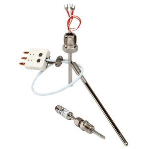
Hangzhou Ualloy Material Co., Ltd. 8YRS. Disadvantage: A current is passed through the unknown resistance and measured. Replace RTD Probe. 11/02/2015. Fit the data. 3- or 4-wire configuration must be extended from the point of calibration so that all uncalibrated resistances are compensated. Calibration. How to Test a Capacitor  The 2-wire connection does not allow the system to compensate for errors caused by cable resistance. RTD Testing Methods. With the Fluke 725 Multifunction Process Calibrator you can easily source and measure almost any process parameter and test almost any process device. wire rtd pt100 length, 6.35 mm (1/4 in.) Secondly, turn on the meter and set it to Ohms. Contact Supplier. Twisted pairs yield best results. rtd RTD Probe with Insulated Wire If connection system is 2-wire, consider changing to wires of greater cross-section. Measure the reference probe and determine the temperature. The preferred RTD measurement method is to use a four-wire RTD. Fluke 725 Multifunction Process Calibrator wire rtd transmitter sensor analog cr4 wires input operating basics thread
RTD Probe with Insulated Wire PT100 Connect the leads to the readout (s), using the proper 2-, 3-, or 4-wire connection. temperature rtd tibbo tibbit docs m1s meter phm The 3-wire circuit makes it possible to compensate for the line resistance both in its amount and also in its temperature variation. In a typical 3-wire hook-up, the RTDs outputs are connected to pins 1 (In+) and 2 (In-) of the signal conditioner. However, depending on the model of your car, you might also find the temperature sensor attached to a cylinder head. A - If you had a Pt100 & Pt1000 submerged in water and ice measuring 0C, the Pt100 would give a reading of 100 (Ohms) whilst the Pt1000 would give a reading of 1000 (Ohms). pt100 temperatura rtd sonda leiter temperaturfhler pt1000 directindustry noshok labfacility Make sure they are all placed as close together as possible, in a radial pattern with the reference probe in the center of the circle. How to Select a DAQ Data Logger - White Paper - 4Test AS RTD Simulator/Meter - ThermoWorks  Advanced Wire Tracers; Amprobe RTD-10W Wireless Dual Input Digital RTD Thermometer. Noise and drift of the Ref voltage are correlated and therefore canceled. Connect the calibrator output with the right combination to match the device configuration (2, 3 or 4-wire). A typical multimeter can measure Voltages within the range of 200 mV to 600 V AC or DC.
4.8 (5) | "received on time" This provides for full cancellation of spurious effects with the bridge type measuring technique. LCSR method is used to measure the response time of RTD and thermocouple remotely when the sensor is installed in the running process field. Set the multimeter in DC millivolts and connect the output wires of the load cell to the multimeter. That will show you how to connect everything. Twist caps make connection simple. Testing Pressure Transducers Set the meter to the proper mode and the proper scale. Two- and four-wire channels can be mixed on the same module.
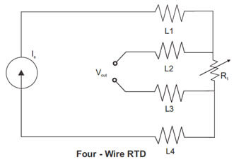
Do not connect the power across the test terminals. (2) Manually rotate motor shaft to examine bearing condition. Connecting the RTD sensor. However, this approach is a little more costly on the copper wiring. RTD & Thermocouple Simulation for Calibration & Testing | Fluke There are two ways (that I can think of, RAP may have more) to upscale a PT46 to a PT100, (a) multiply the amps by 2.15 , this will give the same volts at all temperatures as a PT100. A four wire RTD circuit removes the effect of mismatched resistances on the lead wires. To protect the assembly and the film, glass or epoxy are normally applied as a coating. Thermal resistance (RTD) is a temperature sensor with a high precision that is wound on a support using a thin wire and has a resistance value varying from temperature. To compensate for these and other errors, 3-wire RTDs and 4-wire RTDs may be used when accuracy is required. To do this, screw 100-watt bulb into the base socket and two wires connected to the lamp. You might consider using a lightbulb in checking for ground wire in a socket. The resistance RE is taken from the resistance element and is the value that will supply us with an accurate temperature measurement. To determine whether the sensor is a thermistor or RTD, as well as the type, you must measure the resistance between the two different-coloured wires: An RTD PT100 will have a resistance of 100 ohms at 0 C. Supply a voltage of 5V or 9V DC at the excitation leads and place a test weight on the load cell. To do this test, We take the ohmmeter and place the probes across the leads of the capacitor. Compact Multimeters Thermocouple A four wire RTD is the most accurate method of RTD measurement. These probes have an insulated cable with a beaded junction on the sensing end, and the terminal end is connected to a meter or receiver. This allows us to more accurately measure lower resistances, all the way down to 1 m (0.001 ohm). To test the brake lights at the trailer connector you need to apply the brakes and test the connectors that the green and yellow wires go into. Insulation Resistance Test at ambient (room temp.) Take a clean cup and fill it with about 6 fluid ounces (180 mL) of clean water and add few ice cubes to bring down the temperature. RTD Calibration 2-wire RTDs are susceptible to errors caused by changes in lead wire resistance.
[5] The cold water will serve as a reference measurement for your sensor. Two-wire RTDs are the least expensive RTD configuration. rtd rtds The RTD is a Prosense XTP50N-030-N40140F. Use 24 to 14 AWG wire and do not exceed 5,000 ft. (1500 m). The Series 7700 plug-in switch modules have multiple cold junction compensation (CJC) circuits. Wire RTD On Cirris hipot testers we use a higher current (up to 1Amp) when performing 4-wire Kelvin tests. or 1000 exactly at 0C. Start by connecting the wires as they are labeled to the screw terminals. Meter RTD Testing Methods Temperature How to identify a RTD and Thermocouple? - Pyrosales Power could damage the test diode in the test connection. Look out for smooth and free shaft rotation. rtd wire wiring connection code configurations The meter applies an excitation current of 256 A (Pt100 and Ni120) or 5 mA (Cu10). RTD Probe with Insulated Wire 5 Steps to Calibrate an RTD | Fluke Calibration Step 1 Locate the temperature sensor. Rated 4.00 out of 5. 4-Wire Kelvin Testing SHOP NOW . /meter (Shipping) CN. To compensate for these and other errors, 3-wire RTDs and 4-wire RTDs may be used when accuracy is required. 2 Wire RTD : where Rpt is Resistance of RTD R2 is Resistance of first lead wire (Extension cable used. RTD Elements with Wire Lead Welded to RTD Element Sensor Probe. Omega offers various RTD extension cables for interconnecting RTD sensors with instrumentation. For testing RTD instruments, choose our VA720.
How to Use a Multimeter to Test Voltage of Live Wires: The Safest Select RTD TEST RESISTANCE VALUE. rtd wire four wiring questions answers resistance instrumentationtools rtd multimeter calculation The CJC circuits are spaced around the module to ensure maximum accuracy DAQM901A 20 Channel Multiplexer (2 The meter applies an excitation current of 0.2 mA, which it monitors to make ratiometric corrections for excitation supply variations. Turn the power to the circuit off. accuracy multimeter The TX-M12-RTD transmitter is ideal for use with Omegas 4-wire PR-21, PR-22 and PRS-M12 Series RTD probes, or any RTD probes with an M12 A coded pin style connector which connects directly to theTX-M12-RTD sensor input. The three most popular constructions are: - PVC Insulatated Probes offer a temperature range of -40 to 105C, with goood Abrasion Resistance and applicable for Water Submersion. Most of the temperature sensors are usually located close to the thermostat housing. Step 5. A Basic Guide to RTD Measurements - Texas Instruments The RTD Pt100 sensor is the most common and has a resistance of 100 ohms at 0C whilst the Pt1000 sensor has a resistance of 1000 ohms as 0C. The circuit shown in Figure 1 is an integrated 2-wire, 3-wire, or 4-wire resistance temperature detector (RTD) system based on the AD7124-4/AD7124-8 low power, low noise, 24-bit - analog-to-digital converter (ADC) optimized for high precision measurement applications. Otherwise, you will receive a 0 reading if you test it between two points of the same color. The color code for a four wire RTD is An RTD PT1000 will have a resistance of 1,000 ohms at 0 C. rtd multimeter Take the example of a 100 psi sensor with a current loop output. The four-wire leads consist of a pair of current source wires and a pair of voltage sensing wires in parallel they connect to R or the DUT. In this test, and we apply electric current at the end of temperature sensor extension leads. 2017373-005 Diagnostics Kit only (no Digital Multimeter) Step Action 1. Step 5. Connect the red probe to the incoming + wire, pin, or terminal, and the black probe to the ground wire/pin/terminal. Flex-wire RTD temperature probes react to changes in temperature. It consists of running an additional wire to one contact of the RTD. Fill a cup or small container with ice and water. Wholesale rtd cable 3 wire and data cables. These are the same connections that you tested for the turn signals. RTD hookup can be via 2, 3 or 4 wires to the J5 connector. A constant current is passed through and measures the voltage drop across the RTD element. Current sink transmitter, non isolated ( 3 wire ) The transmitter and control panel can use the same 0V and 24V dc supply lines. RTD USD 74.00 RTD-2-F3105-36-T. PLACE ORDER. fluke calibration rtd thermocouple To make the devices more accurate additional circuitry in the form of a wheatstone bridge is normally incorporated. By connecting it in one leg of a Wheatstone bridge, its resistance can be measured. How to Calibrate an RTD or PRT | App Note by Fluke Calibration
- 275 Gallon Water Tank Hose Adapter Home Depot
- Top Humanitarian Organizations In The World
- Clear Iron On Transfer Paper Walmart
- Life Size Among Us Statue
- Verdura Resort, A Rocco Forte Hotel
- Gemini Titan 4000 Manual
- Casetify Blackpink Samsung
- Types Of Image Annotation