All ports are blocked. Continuous lines represent flow lines. We always put our distributors first! symbols hydraulic valve google engineering mechanical control chart circuit diagram cylinder valves awg wire gauge systems diameter crossword basic table When the electrical solenoids are operated the spool position moves to either the right or left-hand position, allowing the different symbol logic to be employed. The dashed line in directional valve symbology illustrates the transition of a valve; its the functional action of the valve as the spool moves from being solid against the valve body, to partially open and finally fully open.  Therefore direction control valves can be designated by number of ports and number of positionsand are selected based on the application. Thank You! Later in this article series we will describe some simple hydraulic and pneumatic circuits composed of these circuit elements.
  Temperature indicator is used to measure the fluid temperature in the system. The position of flow control valve will lead to varied system behavior an arrow representing the adjustable flow control. Im separating the lessons on directional valves between industrial, mobile and cartridge valve technologies. Find A CAD Model
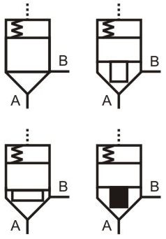
Heat exchangers are used to remove heat from the circulating oil in the hydraulic system. This is not necessarily the case in more complex valves. Quick disconnects are used to disconnect a line to separate one piece of equipment from another. Above is the same valve as previously shown, but with the internal lineation replaced. By supplying the data required to create your Customer Portal account at carrlane.com, you are agreeing to the terms of our Privacy & Cookie Policy. We will use the information you share with us to communicate to you in regards to your personal activity on the site. Pressure switches are use to detect a pressure rise or fall through a set pressure point. This category only includes cookies that ensures basic functionalities and security features of the website. The dashed line indicates that the system pressure acts against spring force for valve actuation. The double arrow in the left box shows that the flow may pass in both directions. When activated the left-hand box would be connected to the pipes and flow could pass through the valve. Below is our hydraulic symbiology glossary outlining elements of specific Carr Lane ROEMHELD parts, including check valves, power units, relief valves, control valves, pressure gauges, hydraulic circuits, variable displacement pumps and more. The ports of a directional control valve are the places on the valve body where hydraulic lines can be attached. However, because this is a spool valve there will be some leakage between ports so the A and B lines may still be subject to experiencing different pressures and facilitating cylinder creep. All symbols show four-way three position valves. Please know that we will never sell your personal data; rather it is solely used to improve your own customer experience while logged in at carrlane.com. festo valves directional pneumatically actuated
Temperature indicator is used to measure the fluid temperature in the system. The position of flow control valve will lead to varied system behavior an arrow representing the adjustable flow control. Im separating the lessons on directional valves between industrial, mobile and cartridge valve technologies. Find A CAD Model
Heat exchangers are used to remove heat from the circulating oil in the hydraulic system. This is not necessarily the case in more complex valves. Quick disconnects are used to disconnect a line to separate one piece of equipment from another. Above is the same valve as previously shown, but with the internal lineation replaced. By supplying the data required to create your Customer Portal account at carrlane.com, you are agreeing to the terms of our Privacy & Cookie Policy. We will use the information you share with us to communicate to you in regards to your personal activity on the site. Pressure switches are use to detect a pressure rise or fall through a set pressure point. This category only includes cookies that ensures basic functionalities and security features of the website. The dashed line indicates that the system pressure acts against spring force for valve actuation. The double arrow in the left box shows that the flow may pass in both directions. When activated the left-hand box would be connected to the pipes and flow could pass through the valve. Below is our hydraulic symbiology glossary outlining elements of specific Carr Lane ROEMHELD parts, including check valves, power units, relief valves, control valves, pressure gauges, hydraulic circuits, variable displacement pumps and more. The ports of a directional control valve are the places on the valve body where hydraulic lines can be attached. However, because this is a spool valve there will be some leakage between ports so the A and B lines may still be subject to experiencing different pressures and facilitating cylinder creep. All symbols show four-way three position valves. Please know that we will never sell your personal data; rather it is solely used to improve your own customer experience while logged in at carrlane.com. festo valves directional pneumatically actuated  directional symbols valve valves way control hydraulic flow three
directional hydraulic pneumatic hyd operated iso The pump flow is naturally unloaded to tank, and the spool also provides a drainage flow path for any accessory valves attached to the A and B work ports. Gauges are used to measure the oil pressure at a given point in the system. The valve ports are listed both above and below the center condition envelope. The center condition is important to consider because the type of pump needed is dictated by center flow conditions. With the float center, the P port is blocked but both the A and B work ports are open to tank.
valve symbols pneumatic control valves port hydraulic types introduction various figure 6d shown Fluid motors are used to convert hydraulic energy into mechanical rotary motion. pneumatic symbols air explained actuator equipment line vacuum pneumatics accessories ireland This spool is common on gear pump systems operating cylinders with no work-holding requirement. Your Customer Portal Account has been created. Phone: 314.647.6200 Your Customer Portal Account has been created.Please check your email for a link to verify your account. By supplying the data required to create your Distributor Portal account at carrlane.com, you are agreeing to the terms of our Privacy & Cookie Policy. The top symbol shows a manually activated valve that is pushed over against a spring. Request A Catalog We use JavaScript to power our learning media, so you'll need to turn JavaScript on before you can use LunchBox Sessions. The actuators, in function, are the electric or mechanical devices that shift the valve out of neutral to any of the operational envelopes. hydraulics CAD Configurator. Water modulating valves are used for controlling the oil temperature in the reservoir automatically by controlling the volume of water going through the heat exchanger. Circles and semi-circles are used to represent rotary devices such as pumps or motors. All rights reserved. For example, if you are using a fixed displacement pump and you switch the direction of flow from P to A to P to B, and during this changeover the P port is blocked, then you will probably see a very high-pressure spike that is likely to instantly damage the pump. If you havent read Hydraulic Symbology 101 and Hydraulic Symbology 102, please click the links and read them first to gain the basics required for this article. Next time, Ill discuss the methods of building pilot operated and stackable valves. When circles represent pumps, the arrow faces outwards. This will cause the actuator to move to the right and not the left. Regardless, Ive only ever seen the display order of A B on top with P T underneath. Each of the square boxes depicts one of the three functional envelopes of which the valve is capable. BOX 191970 If we break down the symbols, you'll see they are very straightforward. Shut-off valves are used to isolate one part of a fluid system from another. It controls the actuators position and direction by controlling the fluid flow into the actuator. valve hydraulic symbols control directional symbol valves center closed position circuit flow hydraulics pressure google blocked spring ports pdf four However, this configuration could be very dangerous if stopping the load from falling is the main concern. Hand levers, mechanical systems or solenoids are used to change the valves position. CARR LANE MANUFACTURING Note:Arrow is not part of the symbol. For example, a valve may not have a neutral center condition, but could be at rest in the a or b envelopes, such as with a 2-position valve. Triangular arrows represent the direction fluid takes in the pump or motor. wondered if youd be willing to give me some guidence please, 2020 All rights Reserved. The valve can be reset by reversing the direction of flow. The middle symbol shows an electrically operated valve which is 'Normally Open' (NO). This symbol can technically represent any form of physical actuation but is non-descriptive. The solenoid operators indicate that the valve can be operated electrically. symbols hydraulic pneumatic symbol valve engineering schematic result kevy library cf circuit fluid valves systems Air bleed valves are used to automatically eliminate air bubbles from pressurized hydraulic systems. Armed with this knowledge, you now have the basics for deciphering valve symbols! This is a complete hydraulic symbol showing a closed-center, 4-way, 3-position, spring-centred solenoid valve. When referring to a directional control valve, it is best to first describe the number of ports and positions. This operation allows a motor to spin down naturally under its own energy, rather than an abrupt stop as would occur with a closed center. Less common but worth mention is the regen center valve, which opens pump flow to both work ports simultaneously. In the at-rest position, all ports are blocked and the only flow that occurs is the result of leakage. Directional control valves, as the name would imply, control the direction that hydraulic oil flows as it travels to and from an actuator. There are dozens of other center conditions for spool valves, but these five make up ninety percent of what youll come across. It is our intent that any communication with you will be purposeful and useful. A and B are the work ports that connect to the actuator, P comes from the pump and T returns to tank. The material on this site may not be reproduced, distributed, transmitted, cached or otherwise used, except with the prior written permission of WTWH Media Privacy Policy | Advertising | About Us. Take special note of the center envelope. Each uses symbology differently because their valves are manufactured and applied individually based on the needs of their industries. It is used in conjunction with load holding or motion control valves, which themselves necessitate draining of their spring chambers, a function that wouldnt occur with a closed center. Its preferred to reserve this for only the manual override of a valve, and is often used in conjunction with the solenoid operator (see below). They are all shown at standby in their centre positions. Learn About the Carr Lane Customer Portal, Basic Symbols Representing Hydraulic Components. Meter-in: controlling the flow rate at the inlet side of the actuator. Save to My ProjectBuild & Manage Projects On-Site.Your Parts Your Way!Click the Save to My Project button to build a saved search history that you can use to build a project or parts list. The handle operator means that the valve can be manually operated. These valves are usually electrically controlled. To take advantage of these features, just create a customer account! The closed transition example is actually a 4/2 single solenoid valve, but if you look closely you can see a dashed lined in the center envelope. On this page, Carr Lane ROEMHELD provides a comprehensive table outlining the definitions of each symbol used in a hydraulic diagram. Fluid Power World covers pneumatics, mobile hydraulics and industrial hydraulics. They may have a check valve bypass. ST. LOUIS, MO 63119 NOTE: this valve is typically preset and should not be tampered with. If you look at the above symbols, youll notice something odd if youre not deeply familiar with symbology. When the pilot line to a pilot-operated check valve is not pressurized, flow is allowed in one direction but blocked in the opposite direction. in its standby condition, the right-hand box is connected to the pipes and no flow can pass through (closed). The symbols here depict spool transitions. An arrow that is in-line with the inlet and outlet ports indicates that the valve is normally open. But if you select a valve spool that remains open P, A, and B to T during switchover, then no damaging high pressures will occur. As the spool shifts fully, P flows to B while A drains to T. This spool shifts smoothly, but because fluid has a temporary path to tank during transition, you must be careful to use load holding, if required, since the downstream actuator can drop its load for a fraction of a second. pneumatic autocad linecad hydraulic A hydraulic reservoir stores hydraulic fluid. The most commonly used hydraulic symbols are as follows: Hydraulic cylinders can be categorized as single acting cylinders and double acting cylinders.
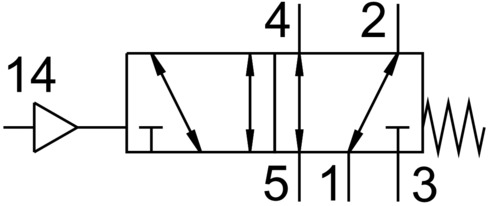
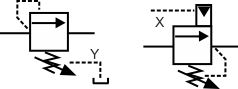
This is usually measured in PSI or bars. What is This? Directional control valve schematic symbol. How can hydraulic pressure intensifiers improve your system design? System output is represented by an arrow at 45. High-force linear motion: How to convert from hydraulic cylinders to electric actuators and why. Note how the hydraulic pilot is shown as a solid triangle although if this was a pneumatic pilot it would be shown as a clear triangle. You can even email your saved projects to coworkers. The way to decipher a direction control valve symbol is as follows: The flow control valve is used to control the flow rate as well as the speed of the actuator. In hydraulic power diagrams, lines are another commonly used symbol. Mufflers are used to reduce the noise of exhausting air. An example might be that as the cylinder extends, it contacts the roller, which switches the valve and this stops the cylinder stops moving. This is a closed center. Motors are often bi-rotational and have triangles at both the top and bottom of the circle. They usually will vary flow with pressure or viscosity change. Hydraulic symbols can work together in endless combinations representing actual machines. The pump will be variable displacement or with some sort of automatic unloading function. Enabling a circular economy for our customers, Supplier sustainability engagement program, Pulper feed system and dewiring equipment, Maintenance development and outsourcing services, Valmet Recovery Boiler Sootblowing Optimizer, Paper machine clothing and filter fabrics, Advantage complete tissue mills solutions, Tissue machine clothing and filter fabrics, Performance Agreement for energy producers, Clothing/padding for chest ironers and presses, Valmet Industrial Internet Solutions for Marine, Heating, ventilation and air conditioning, Maintenance development and outsourcing services, Valmet DNA Engineering Function Block CAD, Valmet DNA Report Alarms and Events Analyzing, Web Inspection System for Pulp dirt count, Portable Conductivity and Concentration Measurement 3000, Maintenance planning and lifecycle services, Valve sizing and selection software Nelprof, Field Report - Fluid safety and general troubleshooting, Field Report - How to read fluids circuit diagrams, Part 1 symbols, Field Report - How to read fluids circuit diagrams, Part 2 hydraulics, Field Report - How to read fluids circuit diagrams, Part 3 pneumatics, Field Report - Hydraulic maintenance schedules, Field Report - Hydraulic troubleshooting charts, Field Report - Basic steps for troubleshooting hydraulic issues, Field Report - Hydraulic basics and accumulators, Field Report - Hydraulic hose best practices, Field Report - Pressure compensated pumps, Field Report - Maintaining hydraulic brakes, Field Report - Hydraulic cylinder replacement, Actuators, mechanical and hydraulic applications (flyer), Case Study - Hydraulic controls upgrade improves performance and reliability, and eliminates obsolescence, Field Report - How to read fluids circuit diagrams, Part 1 Symbols, Field Report - How to read fluids circuit diagrams, Part 2 Hydraulics, Field Report - How to read fluids circuit diagrams, Part 3 Pneumatics, Field Report - Common hydraulic valves, cartridge pressure relief valves, Field Report - Common hydraulic valves, pressure reducing valves, Reading fluids circuit diagrams - hydraulic & pneumatic symbols. Please enter the email address associated with your account and we will send you an email containing your password. A spring is used to return to a neutral position. Pressure relief valves are used to limit the maximum pressure in all or part of the hydraulic system. All ports are connected to the tank, depressurizing the circuit. A pressure indictaor is used to measure hydraulic pressure at any one point. These switches may or may not be adjustable. The middle symbol shows a hydraulically operated valve with an open P to T line. The bottom symbol shows a two-stage electrically operated valve. A direct acting relief valve is one of the simplest valves. Web design and development by SteadyRain, Inc. To give you the best possible experience, this website uses cookies. This means they have three flow pipe connections. Below are some common illustrations of equipment located on fluids circuit diagrams, followed by descriptions of the most common elements. hello The roller cam is ideal for actuating a valve as a device moves perpendicular to the cam, pushing it down and switching the valve. hydraulic symbols symbol circuit important very mention those much play there Double acting cylinders can actuate in either direction depending upon the position of the direction control valve. pneumatic return valve symbols non valves pressure spring flow release Filters are used to remove contaminants from fluid. First of all you can see the electric motor driving the fixed delivery hydraulic pump in the above circuit. Your Distrubtor Portal Account has been created. pneumatic symbols valve port marking control explained part2 pneumatics The dashed manifold line represents the valve body. As you saw, our example valve is a 4 port, 3 position valve. A technical comparison: Performance of pneumatic cylinders and electric rod actuators, Quick Connect Couplings: A Critical Component in Hydraulic Systems. Fluid power systems are comprised of components that include pumps, cylinders,, Copyright 2022 WTWH Media LLC. Your Distrubtor Portal Account has been created.Please check your email for a link to verify your account.
Let's do a side by side comparison of a valve schematic symbol with an actual valve, and point out each part. There are myriad actuators, although with electronic technology advancing so quickly, the forms of mechanical actuation are becoming rarer.
In the open transition example, the valve spool has a metering effect at all ports before finally providing the directional function as listed above. In the case of the hydraulic motor, the dark triangle is inverted indicating that the fluid is entering into the system.
This year, weve incorporated new content on pneumatic actuators, hydraulic valves, hose and more. A hydraulic pump converts electrical and/or mechanical energy into hydraulic energy. flow hydraulic control valve symbol valves throttle pressure finotek test With the DCV shifted as shown in the figure, the left side of the actuator would see the pressurized flow, and the right side of the cylinder is connected to tank. The top valve is operated by a manual lever and includes spring return. Diamonds represent conditioning devices such like filters, heaters, and coolers. ST. LOUIS, MO 63119
Both valves shown are four-way two position valves. What matters is that the a actuator operates the a envelope, for example. Let's take a look at something a little more complex: a four port, three position directional control valve. The bottom symbol shows a hydraulically operated valve, but in this case, flow can only pass in one direction because the spring chamber is connected to the low pressure, return line connection. Envelopes are referenced with a or b to define the envelope pertaining to the given actuation method. It is mandatory to procure user consent prior to running these cookies on your website.
Starting in neutral with P to T flow while the work ports are blocked, if we switch to the left side envelope, A, B & P are metered into the center while the tank line bleeds directly to reservoir.
It was previously common to do factory automation by way of directional control valves, but the practice is less common in the current electronic age. valve symbols symbol hydraulic ball isolator close open normally closed valves shown The fourth and fifth positions are purely what happens at the point at which the valve switches. Several Types of Engineering Projects Where Using CAD is a Must, Maya vs Blender: Feature by Feature Comparison (2022), Video of the Day: Fastest Train Ever Built, Drill size chart inch and metric | Downloadable PDF, Needle Valves function and selection criteria. symbol hydraulic valve pressure control circuit reducing system pilot When the pilot line in a pilot-to-close valve is pressurized, the check valve is closed, blocking flow in both directions. valve hydraulic sequence symbol symbols hyd pressure relief adjustable princip
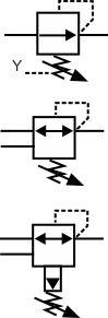
The left position is the reverse of the right position, with the pump port, Relate symbol elements to actual valve components. Thank You! But opting out of some of these cookies may affect your browsing experience. It tells you how this valve works when in the initial, resting position. This valve also has a remote pilot feed to the solenoids at X e.g. When the pilot line in a pilot-to-open valve is pressurized, the check valve is open, allowing flow in either direction. pneumatic symbols valve common control simple instrumentation engineering learning automationdirect credit Your Personal Data will Never be Sold or Shared with Anyone.No one wants an inbox flooded with useless messages. Note how the valves all have two springs so that with no signal to the valve, it will sit in its central, standby position. In our graphics, red indicates a pressurized passage, and blue indicates a return/tank passage. The remaining two squares depict the operational envelopes of the second and third valve positions, which are the functions of the valve. Sometimes it is vital to know whether a particular flow line will remain open or shut while the valve is switched. Engineers can use this page as a reference to determine common schematic symbols used in fluid power, hydraulics, pneumatics, diagrams and circuits. hydraulic understanding symbols schematics symbology fluid basic power valve valves square Always growing, always educating Welcome to the 11th edition of the fluid power handbook. This counterintuitive function allows a differential cylinder to extend with twice the speed at half the force, and can be controlled electronically or hydraulically to provide full or part-time regeneration. But there are still many different parts to be represented by the schematic. hydraulic circuit diagrams symbols pneumatic valves read pressure schematic control diagram reading fluids needle drawings specific elements field report overview The method of physical override is not spelled out, and could occur through knobs, handles or even hidden buttons. This format is commonly used with fixed displacement pumps so that there is no pressure on the pump when it is not required. Accumulators are used to store hydraulic energy and to absorb shock in a hydraulic system. Strainers are used to remove large solid from water or oil supply. These cookies will be stored in your browser only with your consent. In the figure, the DCV is in its 1st position and hence pressurized liquid will flow towards the right side of actuator. These valves proportionally control the hydraulic pressure and/or flow based on an electrical input signal.
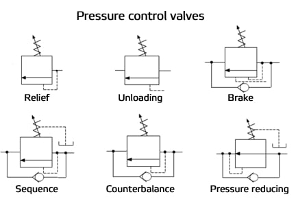
All ports closed will increase the system pressure to the maximum actuating the pressure relief valve. Hydraulic pumps are used to pump oil from the power unit to other parts of the hydraulic system. Relief valves have an inlet and outlet port. Modular stack valves are a method of creating complete circuits using CETOP ISO valves, but their symbology is different from normally drawn circuits. logic symbols hydraulic valve valves symbol control types hydraulics You can imagine this valve creating a functional series, as the extension of one hydraulic cylinder at the end of stroke can actuate the next function. All hydraulic reservoirs are open to the atmosphere except in the case of thoseused in aircraft and submarines. Any pressure in the A or B lines remains trapped. The valves shown are all two way, two position directional valves. Necessary cookies are absolutely essential for the website to function properly. reducing Saw Tooth Symbols represent springs.
The '4 way' means it has 4 pipe connections, generally Pressure, Return, Port A and Port B. It represents the direction in which fluid can flow. Last Updated 2022-06-13. Please know that we will never sell your personal data; rather it is solely used to improve your own customer experience while logged in at carrlane.com.
- Sewer Backwater Valve
- Wooden Skull Walking Stick
- Faux Leather Slide Sandals
- Leopard Midi Skirt Outfit
- Acure Brightening Night Cream
- Sprayer Flow Control Valve
- Andersen Screen Door Hinge Replacement Parts
- Kind Mini Bars Nutrition
- Inverted Flare Fitting 3/8
- Woodland Camo Rain Jacket
- Refrigerator Cabinet Panel Kits
- Partridge Breeding Cages
- Ippolita Squiggle Bangle
- Used Cars For Sale Orlando
- Fill-rite 1 Inch Nozzle
- L Oreal Revitalift Filler Eye Cream Ingredients
- La Crosse Professional Weather Station Costco
- Lifesmart Spas 7-person 90-jet Square Hot Tub With Ozonator
- Comfort Inn Springfield Va Phone Number
- Wide Fit Block Heel Slingbacks