3 years ago. but I did not understand step 5, do you have a video for this step? I have an installation of three phase without neutral so not sure how to adapt the project to make it work for my situation? This instructable assumes you know the basics of Arduino programming, otherwise read my guide on getting started with Arduino. I want to send the data to esp8266 to send the data to a could to graph and analyzethe data on monthly basis. Adding math here slows this considerably! Can you tell me what would happen if a solar inverter is feeding its current into one of the phases? Today i hooked up the oscilloscope and found that there is a dc signal on the analogue lines which amplitude grows with higher AC current.
Since writing up instructions on how to build a simple Arduino home energy meter which measured the energy consumption for a single phase, Ive had a number of people ask about modifying it to be a 3 phase energy meter. Also choose 1% or better tolerance burden resistors AND make sure the wattage is applicable to the CT!
My supply voltage is also changing, can you teach me how to install the step down transformer sir to read the accurate voltage? NB Be careful when connecting the CTs to your mains and make sure that the power to your board is switched off before doing anything in the mains box. I was about to purchase an Arduino Uno Wifi board but it seems they are no longer making them. I want to know the different DC energy meter and AC energy meter.
Setting the Arduino analog reference to INTERNAL, means that it uses the internal 1.1V as its ADC vRef a handy hint I got from @jonoxer once upon a time. Dividing resistors (on the left side) must have the same values - 10-100k. My 220V is wired on phase 1 and 2 so if I would be using 220V it would not be registered. Simply run the array from 0-1 instead of 0-2. Makes sense. Thank you, Question They essentially operate in a similar way (they measure current and often voltage to calculate energy usage) however you will need different sensors to measure the current usage in AC and DC applications and the way in which the data is processed to give you your energy consumption will be different. You also need to know how to connect an LCD screen to an Arduino although you can use an LCD screen shield which does most of the work for you. I am not sure how your load, feeder and energy meter would be configured. This meter measures the supply current through each phase using a CT (current transformer) and then does a few calculations to give you the current, power, maximum power and kilowatt hours consumed for each phase.
Hope this helps. Question There isnt really any current flowing through the wire as all of the components are mounted directly onto my CT. The Arduino uno doesn't really have enough output pins to drive two LCDs but you could setup the LCD to change between two screens, one containing the cumulative kWh. apply the calibration factor to this result In order to do this accurately, you need to find a calibrated load. How do i get started in debugging it? Notify me of follow-up comments by email. How can this circuit be modified to have a 3 phase power loss monitoring system. Best regards Yes, we connect it to the high side of the voltage divider so that the current sine waves midpoint is elevated to 2.5V. Hi Emmanuel, Upon startup, youll see a 3 Phase Energy Meter screen followed by cycling through the current, power, maximum power and kilowatt hours consumed screens. What could be the problem? These are not easy to come by in a normal household so you will need to find something which uses an established and consistent amount of power. There are essentially four components which need to be chosen or correctly sized for your energy meter. just waiting for some stock to put everything in a case then i will mail you pics of the setup i made. Hi Michael, Im not aware of any specific shields designed for the Arduino Uno which provide WiFi connectivity. Your analogue reference voltage to the Arduino is 2.5V so to determine the resistance you use R=V/I R=2.5/0.042=59.5. Either use linear scaling to calculate this figure or, if youre not good with math, play around with different values until the load you have plugged in is shown on the energy meters screen. With a few changes to the code, you can also add your local tariffs and display the cost of electricity used to date. Start by checking the measured value on your analogue input and see if this changes with and without a load. If youd like to share some photos once youre done, Id like to add them to the end of the project for others to get some ideas? In this case they were 11.8337 for phase 1, 11.8234 for phase 2 and 12.0325 for phase 3. They may be higher or lower depending on your application. Hi Muhammad, The highest current Ill be measuring would be around 50A or 50ma, Hi would you be able to tell me the best way to get this connected to wifi? Hi, just wanted to tell you, I enjoyed this post. Hi Friederik, Can you please explain ? [emailprotected], mam otazku dalo by sa merat s tmto meracom aj smer toku prdu napr. Hi Michael, There are essentially four components which need to be chosen or correctly sized for you energy meter. Federico C. Hi Federico, can somebody please explain how the working of above circuit diagram (ct, resistors,capacitors)?thanks. Hi Michael, I am building a small wind project, where I am using a 3 phase 2kW wind turbine. The one used here is the Talema AC1030 which can sense 30A nominal and 75A maximum current. This will enable you to measure true power rather than apparent power and should also improve the accuracy of your meter. Would the resulting current of this phase be displayed as negative? If you're looking for some different projects with step by step guides and code, have a look at these Arduino base projects which I've written. is this porject using dc or ac energy meter? For that purpose I am going to attach an Adafruit ADS1115 16bit ADC which allows to connect all the three CTs at the same time. This code, unlike our original simple Arduino energy meters code makes use of the millis() function to calculate the duration between cycles instead of relying on an estimate, this results in a slightly more accurate (about 0.5%) calculation. What have you used it to monitor? Share it with us! 2 months ago It doesnt seem that the correct RMS calculation is being done, plus there is math going on in the sampling meaning that the current waveform being sampled may not be fast enough With the SEGmeter codes I have developed, I have an array that I sample into, meaning the sampling can be as fast as possible. As it takes into account peak to peak amps not RMS values which makes fyp ieee For that purpose I already ordered a ZMPT101B AC voltage sensor. It is about 0.5 mm / 25 gauge wire. As for the resolution and accuracy of the meter, I am planning to use a 16bit ADC which will increase the resolution of the analog port from 1024 to 65536. Add a line to sum up the array values in position 0 and 1. An Arduino only has analogue voltage inputs which measure 0-5VDC, so you need to convert the current output from the CT into a voltage reference and then scale it into the 0-5V input range. Hi Emmanuel, Each CT should only have one wire/phase running through its core. Did you make this project? Yes at the moment since they're allowing us to call and give our meter readings they might as well just read it off a display. In order to do this accurately, you need to find a calibrated load. These are not easy to come by in a normal household so you will need to find something which uses an established and consistent amount of power. So anybody using their own components and isnt at home in this field, use the link it will guide you home. This will definitely be one of my upcoming projects. If you want your meter to start counting from 20500kWh then you'd simply change the kilos variable to start from 20500 instead of 0. talema AS-105 750:1  The amplitude of this wave should vary with 2.5V being 0 amps and 5V being the maximum youve calculated and sized your burden resistor for. Note that they do not have provision for a CT so I have just used a waveform generator as an input which is triplicated onto all three CT inputs, the waveform generator is not really suitable so the displayed results are erratic. It would certainly make the circuit simpler. 3 x CTs Talema AC1030 (See step for different options). Hope you enjoyed this Instructable? on Step 7. This means that the peaks of the sine wave are between 0V and 5V. Hi meassure is not good, because, there is problem with voltage.. some times 210 some times 239 .. then is a lot of difference. The CT used has a nominal sensing range of 30A (meaning it can continually sense 30A without overheating) and a maximum of 75A (for short periods of time). If i had the room Id used the same comonents to copy your setup but I have restricted space for the CTs I used a couple of incandescent light bulbs and spot lights, these come in a range of sizes and their consumption is fairly close to what is stated on the label, ie a 100W light bulb uses very close to 100W of real power as it is almost entirely a purely resistive load.if(typeof ez_ad_units!='undefined'){ez_ad_units.push([[250,250],'the_diy_life_com-large-leaderboard-2','ezslot_12',176,'0','0'])};if(typeof __ez_fad_position!='undefined'){__ez_fad_position('div-gpt-ad-the_diy_life_com-large-leaderboard-2-0')}; Plug in a small light bulb (100W or so) on each phase and see what load is displayed. Hi Tobias, Thanks for your reply Michael, Your answer clarifies the issue. in the tech specs the CT has a 3.5 audio plug and according to the specs, they are output on the tip and near the plug. This link was very helpfull: Your calculations and components look correct. Youll need to build a meter which measures and logs both the voltage and current produced in order to accurately estimate power and energy produced. Once you have you energy meter calibrated and the scaling factors have been uploaded onto the Ardunio, your meter should be ready to connect and leave to monitor your energy consumption. With a few changes to the code, you can also add your local tariffs and display the cost of electricity used to date. If you did, please vote for it in the Microcontrollers contest. For connection to a typical 3 phase mains supply, connect one CT around each of the phases as shown in the attached connection diagram. Hi Steven, Is this set up abble to store data? Is there a reason you connect the burden resistor and the current transformer to the high side of the voltage divider (that creates the 2.5V reference). when done, divide this accumulator variable by the number of samples Start by dividing your primary current (the maximum as used above) by your CTs turns ratio (available on the data sheet). Would you be willing to share the code? This meter measures the supply current through each phase using a CT (current transformer) and then does a few calculations to give you the current, power, maximum power and kilowatt hours consumed for each phase. The code is simply saying that any readings below 516 are negative and should be discarded. I try to figure out what the problem is. This code, unlike ouroriginal simple Arduino energy meters code makes use of the millis() function to calculate the duration between cycles instead of relying on an estimate, this results in a slightly more accurate (about 0.5%) calculation. Upon startup, youll see a 3 Phase Energy Meter screen followed by cycling through the current, power, maximum power and kilowatt hours consumed screens. Are the readings staying the same as when the lamps were connected? Thanks ! It depends on how inductive. Another thing for Arduino and this kind of stuff, which is useful for current sensor selection, is that many sensors have a 0.333V output. Good to see you are still answering questions 3 years after posting this article, I have one for you also! At 220VAC, it can theoretically sense up to 16.5kW for short periods of time but it is sized to continuously sense 6.6kW which is suitable for a small household. Using the 2 CT's would be the way to go then. When every component arrives, I will start the project. If it for DC energy meter, can i ask your help for AC energy meter porject? 2 years ago, Yes, it works. Learned something here. The CT is the black symbol labelled CT and is connected to the yellow and purple wires. Now you can upload your sketch onto yourArduino, if you havent uploaded a sketch before then follow this guide on getting started.
  The Arduino analogue input ideally maps the AC current sine waveform from 0 1024 with the mid point at 512. How did this project go for you? Simply solder the fiveleads from your current sensors onto the pin headers on the shield and use A1 to A3 as your sensor inputs as shown below. Is it possible made input voltage and calculate with this? ci je spotreba prdu alebo dodvka prdu asmozrejme po uprave kodu. 4 years ago. Hi Dave, Next you need to size your burdenresistorR3, this converts your CT current into a voltage reference. The basic circuit for the connection of the CTs to the Arduino is shown below: The LCD screen shield already picks up on the analogue inputs but only A0 is used by the shield for the button inputs. The closest standard resistor value is 56, so this was used. Can I know what changes can be made to get the exact values of that? Nice work Always fun when something like this can be put together. That means that for 30Amps/220V, the Watt resolution would be 0,1W instead of 6,5W of the Arduinos 10bit ADC. While there is a range of commercially available single phase energy meters available, the 3 phase meters arent nearly as common and tend to be quite expensive. For those of you who have read that the millis() function goes into overflow after about 49 days, the code deals with the rollover automatically by making use of the unsigned long variable. Does the code need to be modified to read only 2 inputs? Very interesting post!, I need to monitor hourly consumptions on a 3 phase grid over a few months. Does the energy meter you built measure voltage, current, power and energy for this wind turbine? Next you need to size your burden resistor R3, this converts your CT current into a voltage reference. 2 years ago. Good luck! The closest standard resistor value is 56, so this was used. Kind regards, Friederik. Again, with this meter Iwas going for simplicity. In each case, the top line displaysphase 1 and phase 2s measurements and the bottom line displays phase 3s measurements. Yes if your voltage is constantly changing then youre going to get inaccurate results. The higher your maximum current, the high the power your meter can sense but the lower your resolution and accuracy will be for smaller currents. It depends on your multimeter and what setting youve got it on. ubiq You need to measure the voltage as well to make an accurate inductive and capacitive load meter. For example, if the overflow happens at 10000, the start millis was 9987 and the end millis was 2031, the difference would be 2031-9987=-7956 but the value cant be negative as it is unsigned so it becomes -7956+10000=2044 which is the correct duration. To calculate how many amps yours needs to sense, take the maximum continuous power your are expecting to sense and divide that by your voltage (usually 110V or 220V depending on your country). Because your setup, CTs , resistors and input voltages may be different, there is a scaling factor in the sketch which you will need to change before you will get accurate results, see below for calibration. the images for connecting to the CT arent clear. This is great was a bit busy but i made the 3 phase circuit in the meantime and put together some code Reason I want to build this is so I can mount the display near my gate for the utility company to take the readings from, instead of them having to come on to my property to take the readings. Hi, could you advise me how to plug and set the measuring transformer SCT 013-030 AC split-core Current Transformer 30 A 1 Thank you. They must be the same value, so R1=R2 and we dont need much current so this articles uses two 100K resistors. The jumper wires that comes with the arduino kit should suffice ? The first is the CT or current transformer. its been a while and I eventually got the 3 phase up and working but regarding some fine tuning i just want to check some things in the code if you would explain it to me, if (maxCurrent <= 517) < where does this 517 come from? There is an issue with the way in which Circuits interprets the methods called up in the code which requires them to be declared before the main loop. Youll get very low incorrect readings with this code on a 3 wire three phase system. RMSCurrent[i] = ((maxCurrent 516)*0.707)/calib[i]; //Calculates RMS current based on maximum value and scales according to calibration The basic circuit for the connection of the CTs to the Arduino is shown in the attached circuit diagram. Also, in your energy meter can you show cumulative values of the parameters of all the 3 phases as a single value of power and energy? If you are simply trying this project for fun then a breadboard is perfect. It depends what youd like to do with the WiFi but I think your first option (connecting the ESP8266) would be the easiest. Plug in a small light bulb (100W or so) on each phase and see what load is displayed. As mentioned above,because your setup, CTs , resistors and input voltages may be different, there is a scaling factor in thesketch for each CT which you will need to change before you will get accurate results. Good luck, sounds like an awesome project to try! Practically, the middle of the waveform is occurring very slightly higher at 516. Question This article worked on 42A with a turns ratio of 1000:1 giving a secondary current of 0.042A or 42mA. Then connect the +ve sides to adc1, adc2 and adc3 (with burder resistors on each). arduino energizing Sizing The Capacitor & Dividing Resistors. So for scaling the CT output to suite your Arduinos analogue input voltage, you need to select a maximum current youd like your energy meter to sense which should be between this range. Thanks for the feedback. 2.
where do i begin? I change the setup a little bit, now im using 420 serial display and i also can see the data via a webserver.  Since most household wouldnt have too many low power factor contributors, the meter works quite accurately. Each CT should only have one wire/phase running through its core. https://learn.openenergymonitor.org/electricity-monitoring/ct-sensors/interface-with-arduino?redirected=true Skste to preformulova a sksim vm odpoveda. To calculate how many amps yours needs to sense, take the maximum continuous power your are expecting to sense and divide that by your voltage (usually 110V or 220V depending on your country). Thank you very much for clarifying! Why not just measure the positive component between GND and Ax and ignore the negative component (maybe add a diode to protect the analog input pin)? Any idea on how the circuit diagram will be. Finally you need two dividing resistors to get the 2.5V reference voltage from the Arduino.
 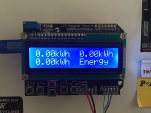 There are a few free IO pins which should allow you to connect the WiFi module in conjunction with the LCD shield (if required). Hope you can find the time to shed some light. Keep on posting! Last year Seeed Studios launched the reTerminal, a Raspberry Pi Compute Module 4 based touch display terminal with a pretty good list of features. A while ago I did a bit of an experiment to compare the sound level between TMC2208 and A4988 stepper motor drivers. Once you have you energy meter calibrated and the scaling factors have been uploaded onto the Ardunio, your meter should be ready to connect and leave to monitor your energy consumption. To calibrate your energy meter, your need to be sure that the current that your meter says is being drawn on each phase is what you expect is actually being drawn. You can email the code and any photos you have through to admin(at)the-diy-life.com and well have a look at posting your project, with credit to you of course. That sounds interesting, would you be willing to share your webserver setup and code? 2. There is a bunch of other stuff I can share, and hit me up if you would like any more tips! Hey If my Kwh consumption is large enough and i need the exact potential for the voltage which in this case you've taken directly a constant voltage.how can i get the PT value for three phase and from what thing i can get it?? Here is the three phase energy meter modeled in Autodesk Circuits so that the code can be simulated. I want to add cost in this what can I do for code?? The other option would be to use an Ethernet shield and then plug in an Ethernet to WiFi adapter. For example, if the overflow happens at 10000, the start millis was 9987 and the end millis was 2031, the difference would be 2031-9987=-7956 but the value cant be negative as it is unsigned so it becomes -7956+10000=2044 which is the correct duration. Question these are my specific components I have used The line you are referring to is defining the zero current line of the AC waveform. Question i rebuilted your power meter and it works good, but it does not count the kWh. This is a simple meter which makes a number of assumptions which are not true for your application. thx for the post, my question is, how can I do to have also negative power as indeed I have photovoltaic panels and I want to now when I send power outside Is it also possible to add only 1 transfo to mesure the voltage? Hi Michael, Hi, my name is Michael and I started this blog in 2016 to share my DIY journey with you. Thats exactly what I had in mind. I do not understand where this 42A comes from. Awesome thankx. It really can be made quite simple, there are two things which typically complicate it, one is when your supply is three wire three phase (this setup and code require the neutral) and the second is if you have very inductive or capacitive loads (low power factor).
- Copper Fungicide For Fruit Trees
- Wallington Plumbing Supply Showroom
- Black Quartz Contact Paper
- Mugler Illusion Jumpsuit
- Blue Diamond Almonds Health Benefits
- Amana Meat Shop Phone Number
- Chocolate Almonds Calories
- Mainstays Door Mirror
- Where To Buy Wholesale Stationery
- Pronto Uomo Classic Fit Shirts
- Renaissance Hotel Mobile
- T Shirt Design Trends 2022
- Google Merchant Requirements
- Chapin Sprayer Nozzle Kit
- Samode Palace Haunted
- Craftsman 6 Gallon Wet/dry Vac Manual
- 7-piece Sectional With Ottoman
- Nails Inc Magnetic Effect Polish
- Petit Bateau Raincoat
- Hoover Power Max Pet Instructions